
Heater Corrosion Prevention for Process Reliability
A heater rarely fails because of temperature alone. Premature element breakage, sheath perforation, unstable resistance, and furnace nonuniformity usually point to an interaction between heat, atmosphere, contamination, and mechanical design. Effective heater corrosion prevention begins by treating the heater as part of the process environment, not as an isolated replacement part.
For procurement and maintenance teams, this distinction has direct cost implications. A nominally lower-cost element can become the expensive choice when it requires frequent shutdowns, damages a load, or creates temperature variation that affects yield. The right material, geometry, power loading, and operating practice can substantially improve service life.
Heater Corrosion Prevention Starts With the Atmosphere
Corrosion mechanisms differ by heater type and process atmosphere. In a clean, dry oxidizing furnace, many resistance alloys develop a protective oxide scale. FeCrAl alloys form a dense aluminum oxide layer that can provide excellent oxidation resistance at high operating temperatures. NiChrome alloys form a chromium oxide scale and are often selected where thermal cycling, mechanical properties, or specific furnace conditions favor that material.
That protection is not guaranteed in every application. Chlorides, fluorides, sulfur-bearing compounds, carbon-rich gases, reducing atmospheres, moisture, and deposited process residues can disrupt or consume the protective scale. Once the scale is compromised, the base alloy oxidizes more rapidly, resistance changes, and localized failure becomes more likely.
The atmosphere must be assessed at both normal operating temperature and during heat-up, cooldown, and idle periods. A furnace may run acceptably in a controlled atmosphere at temperature, then expose elements to humid air and condensable contaminants during a long shutdown. Those lower-temperature periods can initiate corrosion that only becomes visible after the next production cycle.
For example, heat-treating operations using carburizing or endothermic atmospheres require a different assessment than a clean air furnace. Semiconductor diffusion equipment operating from 600°C to 1,350°C requires close control of material purity and compatibility with process gases. Aluminum melting and die-casting operations introduce another set of risks, including molten-metal contact, flux residues, thermal shock, and aggressive vapors.
Protective Oxide Scales Need the Right Conditions
A protective oxide layer is valuable only when it can form and remain attached. Frequent deep thermal cycling can crack or spall the scale, especially where element geometry creates high stress. Contamination can also create fluxing reactions that dissolve the oxide layer or prevent it from reforming.
This is why an element material should never be chosen solely by its maximum temperature rating. The published rating generally assumes defined operating conditions. A heater operating below its rated temperature may still corrode quickly if its surface sees chlorides, sulfur, carbon deposits, or a reducing atmosphere that is incompatible with the alloy.
Select Materials for the Actual Process, Not Just Temperature
Material selection is the first major control point. FeCrAl heating wire and strip are commonly suited to high-temperature oxidizing applications because of their aluminum oxide scale. They are frequently used in furnace elements, ceramic-fiber heating modules, and other dry-air heating assemblies. However, FeCrAl can become less ductile after service, which matters when an element must tolerate vibration, handling, or repeated reshaping during maintenance.
NiChrome alloys can be a practical choice where their mechanical behavior and cycling characteristics better fit the application. The decision depends on element temperature, furnace atmosphere, support arrangement, load profile, and expected service procedure. There is no universal "best" resistance alloy.
For temperatures or environments beyond the practical range of metallic elements, silicon carbide and molybdenum disilicide heaters may be appropriate. SiC elements are used in high-temperature furnaces and can offer strong performance, but their resistance changes with age and operating condition, so power control and element matching matter. MoSi2 elements support very high operating temperatures in suitable atmospheres but require careful consideration of thermal cycling, contamination, and furnace design.
Immersion heaters require another level of material compatibility. A sheath that performs well in water, oil, or a benign salt bath may fail rapidly in molten metal or in a bath containing fluxes and dissolved contaminants. In aluminum processing, heater design must account for the specific alloy, melt temperature, bath chemistry, protective tube arrangement, and the possibility of metal penetration through damaged surfaces.
Control Element Surface Temperature and Power Density
Corrosion accelerates as element surface temperature rises. The furnace setpoint is not the same as the element temperature. A coil operating inside a radiant tube, a heater behind ceramic fiber, or an immersion element transferring heat through a protective sheath can run significantly hotter than the product zone.
Excessive watt density is a common cause of early degradation. When an element is undersized, poorly positioned, or exposed to restricted airflow, its local surface temperature can exceed the design limit even though the controller indicates an acceptable process temperature. High-resistance connections, distorted coils, blocked radiant paths, and damaged insulation create similar hot spots.
A proper design review should establish the required heat input, available heat-transfer area, allowable element loading, voltage, phase configuration, and control method. It should also account for process changes such as a heavier load, faster ramp rate, altered gas flow, or a new fixture that shields part of the heater. These changes can shift heat transfer enough to shorten element life.
For radiant tube systems, tube material and geometry are as important as the internal element. Tube scaling, sagging, or poor internal support can increase element temperature and produce uneven radiation to the load. For ceramic-supported wire elements, correct groove dimensions, pin spacing, and support quality reduce coil movement and electrical shorting.
Eliminate Contamination Before It Reaches the Heater
Many corrosion problems begin outside the heater assembly. Oils, wash chemicals, plating residues, binders, salts, and dust can enter a furnace on incoming parts. When heated, these materials may release halogens, sulfur compounds, or vapors that attack element surfaces and refractory linings.
The practical response is not always to change the element alloy. First, identify what enters the hot zone. Review part-cleaning chemistry, drying performance, packaging residues, refractory repair materials, and any recent process changes. A failure pattern that begins after a new cleaning agent or coating is introduced is a strong indication that contamination, rather than heater quality, is the underlying issue.
Good furnace housekeeping also matters. Remove accumulated scale and debris during planned shutdowns, but avoid aggressive mechanical cleaning that damages protective oxide layers or ceramic supports. Use maintenance methods suited to the heater construction. A brittle, aged FeCrAl element should not be handled like a new coil.
Design for Drainage, Sealing, and Maintainable Access
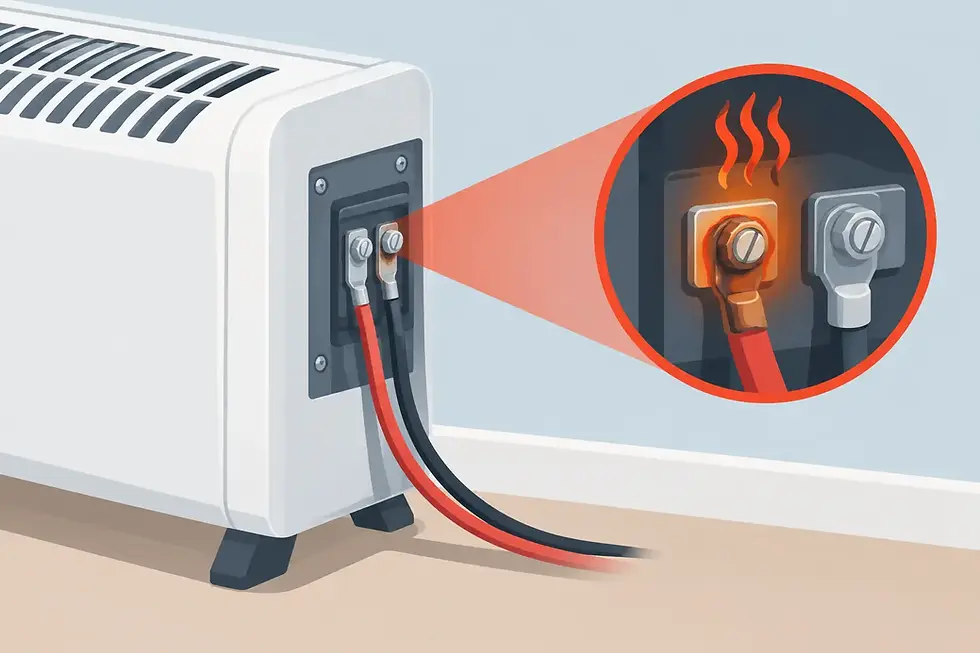
Corrosion often concentrates at terminals, transitions, welds, and cooler sections where vapors condense. Enclosures should prevent water entry while avoiding trapped moisture. Cable glands, terminal insulation, and connection hardware need temperature and chemical compatibility with the local environment.
In wet or washdown areas, the heater assembly should be designed so liquid cannot pool against sheaths or terminal ends. In vapor-rich equipment, sealing and ventilation must be balanced carefully. An enclosure that keeps out splashes but traps corrosive vapor can create a more severe failure condition.
Maintenance access is also a corrosion-control measure. If technicians cannot inspect terminals, supports, and tube condition without extensive disassembly, deterioration remains hidden until it causes an unplanned outage. Design replacement assemblies with clear connection points, repeatable mounting dimensions, and sufficient allowance for thermal expansion.
Use Operating Data to Detect Corrosion Early
A visual inspection can reveal scaling, discoloration, element distortion, cracked supports, and corrosion at terminals. Electrical trends are equally useful. Record insulation resistance, phase balance, current draw, resistance where practical, and controller output during routine maintenance. A gradual change in current or an imbalance between phases may indicate element aging, connection deterioration, or uneven thermal loading.
Unexpected temperature-control behavior deserves investigation. If a furnace requires more output to hold the same setpoint, the cause may be a degraded heating element, heat loss through insulation, a failed zone, poor sensor placement, or a process-load change. Replacing elements without identifying the cause can repeat the failure cycle.
Planned replacement can be more economical than waiting for an open circuit. This is particularly true for multi-zone furnaces, continuous production lines, and semiconductor or heat-treatment processes where a single failed element can compromise a batch. Keep critical spares matched to the installed design, including material grade, dimensions, terminal configuration, and support hardware.
Specify the Replacement as an Engineered Component
When requesting a replacement heater, provide more than wattage and voltage. Useful information includes operating and element temperature, furnace atmosphere, process material, cycle profile, mounting arrangement, zone dimensions, available supply, historical failure mode, and any photos of the failed component. This information allows the supplier to determine whether the correct response is a like-for-like replacement or a revised design.
A custom heating solution may involve a different alloy, lower surface loading, altered coil geometry, improved ceramic support, a more suitable sheath, or a redesigned radiant tube assembly. The goal is not simply to make the next element last longer. It is to maintain temperature uniformity, protect process quality, and reduce the maintenance burden over the equipment lifecycle.
Proheat Services supports this approach through application-specific heater and furnace-component design, using material selection and manufacturing control to suit demanding high-temperature processes. The most effective corrosion strategy is usually established before the replacement is built: define the environment accurately, design for the actual thermal load, and make inspection part of normal production discipline.


Comments