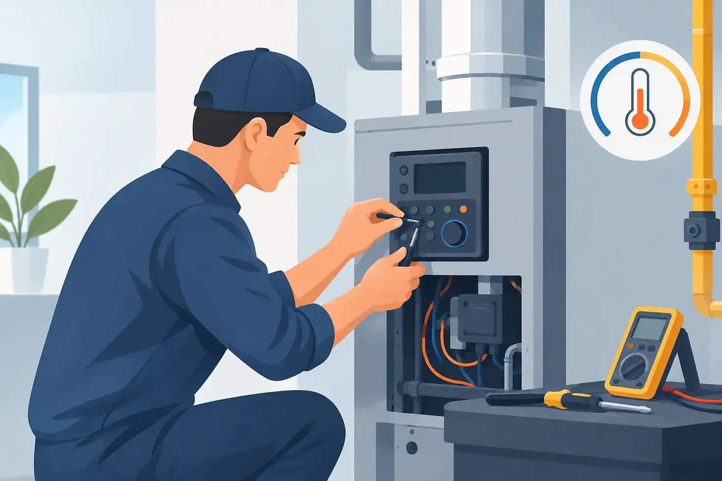
How to Calibrate Furnace Controllers Correctly
A furnace display reading 1,000°F does not prove that the load, work zone, or heating elements are operating at 1,000°F. To calibrate furnace controllers correctly, maintenance teams must verify the entire measurement and control path: the sensor, extension wiring, controller input, output signal, and actual furnace response. That distinction matters when a few degrees can affect heat treatment hardness, alloy oxidation, semiconductor yield, or product traceability.
For industrial furnaces, calibration is not simply a periodic adjustment to make a display agree with a handheld meter. It is a controlled comparison against a known reference, followed by documented correction or replacement where needed. A sound program reduces process drift before it becomes rejected production, excess fuel or electrical consumption, or an unplanned shutdown.
What Furnace Controller Calibration Actually Verifies
A furnace controller receives a temperature signal, compares it with the programmed setpoint, and switches or modulates power to maintain the required process temperature. Calibration confirms that the displayed and controlled value corresponds to a traceable reference over the operating range that matters.
This must be separated from temperature uniformity testing. A controller may read accurately at its sensor location while the furnace has hotter or cooler zones caused by element aging, poor airflow, damaged insulation, load arrangement, or a failing circulation fan. Likewise, a uniform chamber cannot compensate for a controller that is reading 20°F low.
In most plants, the work should address three related checks:
The controller input accuracy, using a certified signal source or simulator.
The thermocouple or RTD measurement loop, using a reference sensor at the furnace.
The furnace's process performance, including stability, overshoot, recovery, and temperature uniformity where the specification requires it.
The correct level of testing depends on the process. A batch furnace used for general stress relieving may tolerate a broader operating band than a diffusion furnace, pharmaceutical oven, or aerospace heat-treatment furnace operating under documented quality requirements.
Before You Calibrate Furnace Controllers
Start with the furnace documentation. Confirm the controller model, input type, sensor type, temperature range, engineering units, control mode, alarm settings, and available calibration offsets. A Type K thermocouple configured as Type N, for example, can create significant error even when the controller itself is functioning properly.
Review the last calibration certificate, maintenance history, production deviations, and any recent replacement of thermocouples, heaters, power controllers, or wiring. These records often show whether the issue is gradual drift or a fault introduced during maintenance.
Use reference equipment appropriate for the required uncertainty. A calibrated dry-block calibrator, temperature source, precision millivolt simulator, or reference thermometer with a suitable probe may be used depending on the test. The reference instrument should have a current calibration certificate and adequate accuracy relative to the furnace tolerance. Testing a tight process tolerance with a marginal reference device creates false confidence.
Plan the work around safe furnace conditions. Isolate electrical power when accessing terminals, follow lockout/tagout requirements, and allow hot surfaces to cool where necessary. Do not disconnect a thermocouple or open a panel in a live high-temperature operation unless the procedure, equipment, and qualified personnel specifically support that task.
Define the acceptance criteria first
Do not decide whether the furnace is acceptable after seeing the results. Establish the allowable error before testing. The acceptance limit may come from a customer specification, internal quality procedure, heat-treatment standard, equipment manufacturer recommendation, or process validation record.
Select test points that reflect actual use. For a furnace operating mostly between 1,650°F and 1,850°F, a check only at room temperature and 500°F is of limited value. Test low, normal, and high operating points, including the most critical setpoint where practical. For a controller used up to 2,372°F or 1,300°C, verify that both the sensor and reference equipment are suitable for the upper range.
A Practical Procedure to Calibrate Furnace Controllers
The preferred method depends on whether the goal is to check the controller electronics alone or the installed system. Both are valuable, but they answer different questions.
1. Inspect the sensor and wiring
Inspect the thermocouple protection tube, ceramic insulators, terminal connections, extension cable, and compensating cable. Look for oxidation, cracked ceramics, loose terminals, moisture ingress, damaged insulation, and incorrect polarity. Thermocouple drift is common in sustained high-temperature service, especially where the atmosphere is oxidizing, reducing, carburizing, or contaminated.
Check that the installed sensor construction suits the application. A sensor selected for intermittent furnace duty may not maintain accuracy in continuous high-temperature service. In demanding environments, the sheath, protection tube, wire gauge, and sensor placement all affect service life and response.
2. Check the controller input with a simulator
Disconnect the sensor input only after recording the existing wiring arrangement and following the approved shutdown procedure. Connect a calibrated simulator configured for the same thermocouple type or RTD curve as the controller. Apply known values at the selected test temperatures and compare the controller display with the simulated value.
If the controller has an allowable input offset and the error is stable and within adjustment range, apply the manufacturer-approved correction. If error varies materially across the range, do not mask it with a single offset. Investigate the controller input card, configuration, or reference junction compensation, and replace the component if required.
Record the as-found values before making any adjustment. These readings are often more useful than the final values because they show whether the equipment was controlling production within tolerance before maintenance.
3. Check the installed measurement loop
Reconnect the sensor and place a traceable reference probe as close as practical to the control thermocouple location. Allow enough soak time for both sensors to stabilize. Compare the controller indication, reference temperature, and programmed setpoint at each test point.
A difference at this stage may come from sensor drift, thermal gradients, poor sensor placement, extension-wire errors, or the controller itself. If the controller passed the simulator test but the installed loop does not agree with the reference, replacing or repositioning the process sensor is often more appropriate than recalibrating the controller.
Avoid placing the reference probe in a different thermal zone and treating the difference as controller error. In a large chamber furnace, a probe near the door or wall can legitimately read differently from one near the control sensor.
4. Verify control behavior under load
After measurement accuracy is confirmed, run the furnace at representative production conditions. Observe heat-up rate, overshoot, cycling, recovery after door opening, and stability around the setpoint. A controller can be calibrated correctly yet still control poorly because of unsuitable PID settings, a failed solid-state relay, undersized heaters, or excessive thermal losses.
Tune PID parameters only after the sensor loop is verified. Tuning a controller around a drifting thermocouple may temporarily improve the chart while hiding the actual fault. For furnaces with changed loads, new heater elements, or altered insulation, PID retuning may be justified because the thermal response has changed.
Calibration Is Not a Substitute for Uniformity Testing
When product quality depends on all workpieces reaching a defined temperature, conduct a temperature uniformity survey using multiple calibrated sensors. This identifies cold and hot zones that a single control sensor cannot detect.
Uniformity issues frequently appear after element replacements, refractory repairs, fan maintenance, or changes in rack design. They can also result from mixing heater materials or geometries with different resistance and radiant characteristics. For example, a replacement element may provide the correct total power but distribute heat differently across the chamber.
For electrically heated furnaces, evaluate the condition and balance of heater circuits. A partial element failure, phase imbalance, loose power connection, or deteriorated radiant tube can create zone-specific variation long before the controller reports an alarm. Customized heating elements and furnace components should match the original operating voltage, wattage, element material, mounting arrangement, and temperature environment.
Set a Calibration Frequency Based on Risk
There is no universal interval for every furnace. A low-risk utility oven may be checked annually, while tightly controlled thermal processes may require more frequent verification, particularly after repair or a process deviation. Increase calibration frequency when the furnace operates near its maximum temperature, uses sensors exposed to corrosive atmospheres, shows repeated drift, or supports regulated production.
Trigger an additional calibration check after controller replacement, sensor replacement, wiring work, major refractory repairs, heater upgrades, power-control changes, or any unexplained quality issue. A documented event-based program is often more effective than relying only on a calendar interval.
Build Records That Support Maintenance Decisions
A useful calibration record includes the furnace identification, controller model, sensor type, test date, reference equipment identification, test points, as-found and as-left values, acceptance criteria, adjustments made, technician, and next due date. Include observations such as damaged thermocouple insulation, unstable readings, or unusually slow recovery.
Trend these records. A sensor that drifts steadily at each interval should be replaced before it reaches the process limit. A controller that repeatedly needs large correction may require repair or replacement. This approach turns calibration from a compliance task into a practical maintenance tool.
For high-temperature operations, the best calibration result is one that holds under real production conditions. Accurate controls, correctly specified sensors, stable power delivery, and heating elements matched to the furnace design give maintenance teams a dependable basis for consistent thermal processing and fewer avoidable interruptions.


Comments